
Accelerate Design Flow with Optenni Lab – Volume II
Posted by Olli Pekonen | 16 April 2024
Introduction
In this Optenni blog article, the themes introduced in the previous blog on Feb 12th, 2024 will be expanded to multiport antennas, in particular to tunable antennas. We also rely on the teachings of an Optenni blog article on preassessments from Nov 28th, 2023.
Antenna to Study
Let’s take a look into a schematic representation of an aperture tuned antenna in the figure below.
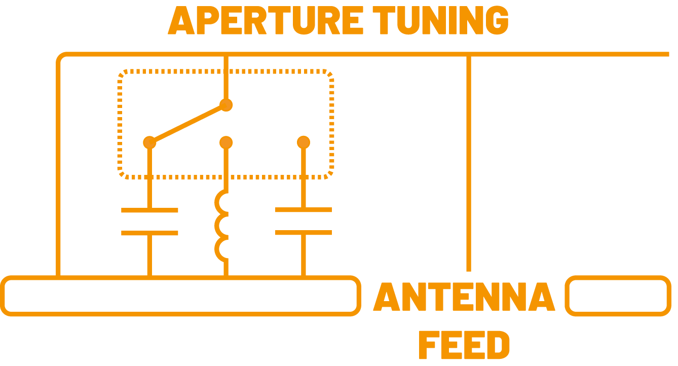
In the picture, there is a simplified view of a three-throw switch with two capacitors and an inductor as tuning component in a tuning port (let’s call this port 2), and the Antenna feed port (to be called port 1), to which the matching circuit is to be connected. Let’s further assume that this antenna is to be used at three different bands, calling them low band (700 – 800 MHz), mid band (1800 – 2000 MHz) and high band (2600 – 2900 MHz), as implied by the three throw port components.
At first blush, the design of this kind of an antenna seems simple in conventional RF circuit simulators, at least if we perform the optimization of the device in the return loss sense, and not in the efficiency sense. Just minimize the S11, and we are done, right?
Well, how are you going to treat the tuning components and the states of the switch? How about just looping them all through, one optimization for one band, a total of three, with the target of minimizing S11.
This rises three further questions:
- Q1: How do you really know if the component in the tuning port is going to be an inductor or a capacitor, even if you get its value optimized?
- Q2: With the three proposed optimization runs, you will get three different matching circuits for the feed port. But you only can have one, catering for all the three bands and the three tuning components (through the states of the switch) at the same time. How to cope with this?
- Q3: And how would you synthesize the topology of even one matching circuit, and not resort to guessing and optimizing the values of the components of a fixed topology, which is also based on a guess?
The answers are as follows:
- A1: In general, you do not. You have to try everything out, 23 = 8 times for three inductors or capacitors.
- A2: Frankly, the only answer we know is: Use Optenni Lab… namely, the current RF circuit simulators are not well suited for this kind of a problem.
- A3: See A2.
Of course, with Optenni Lab, you would do the design to maximise the total efficiency, not just focus on S11. Remember that you get excellent S11 with a lossy system, with a 50 Ohm resistor in the extreme. Obviously, this is not the path we should take.
Using Preassessment Results
It is good to remember that Optenni Lab has preassessment tools for the antenna data which can be used even before any matching circuit design is attempted. We covered this already in our blog article on 28th November 2023 (which conveniently relates to the same antenna) .
With the teachings of the said blog, we know that for the high band, we can likely cope with a simple short circuit as the tuning component, for the mid band we are best off with a small inductor, and for the low frequency, Optenni Lab should choose. This kind of preassessment will save us a lot of time, as nothing is to be optimized for the high band, and no capacitors need to be considered for the mid band.
Posing the Design Task to Optenni Lab
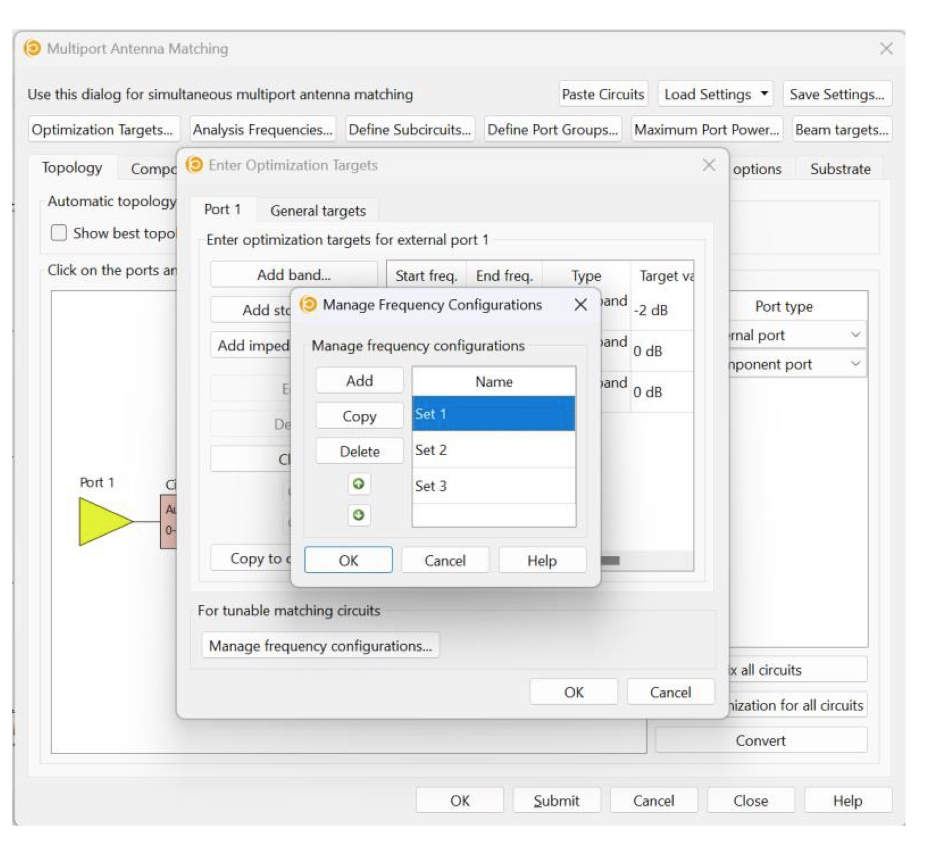
The secret of Optenni Lab handling the various bands each having a different tuning component, and a same matching network so smoothly is called a “frequency configuration”. You simply make three frequency configurations in the Optenni Lab interface, in the Multiport Antenna Matching mode (for example), as show in the figure below. We call the frequency configurations set 1, 2 and 3 for low, mid and high bands, respectively.
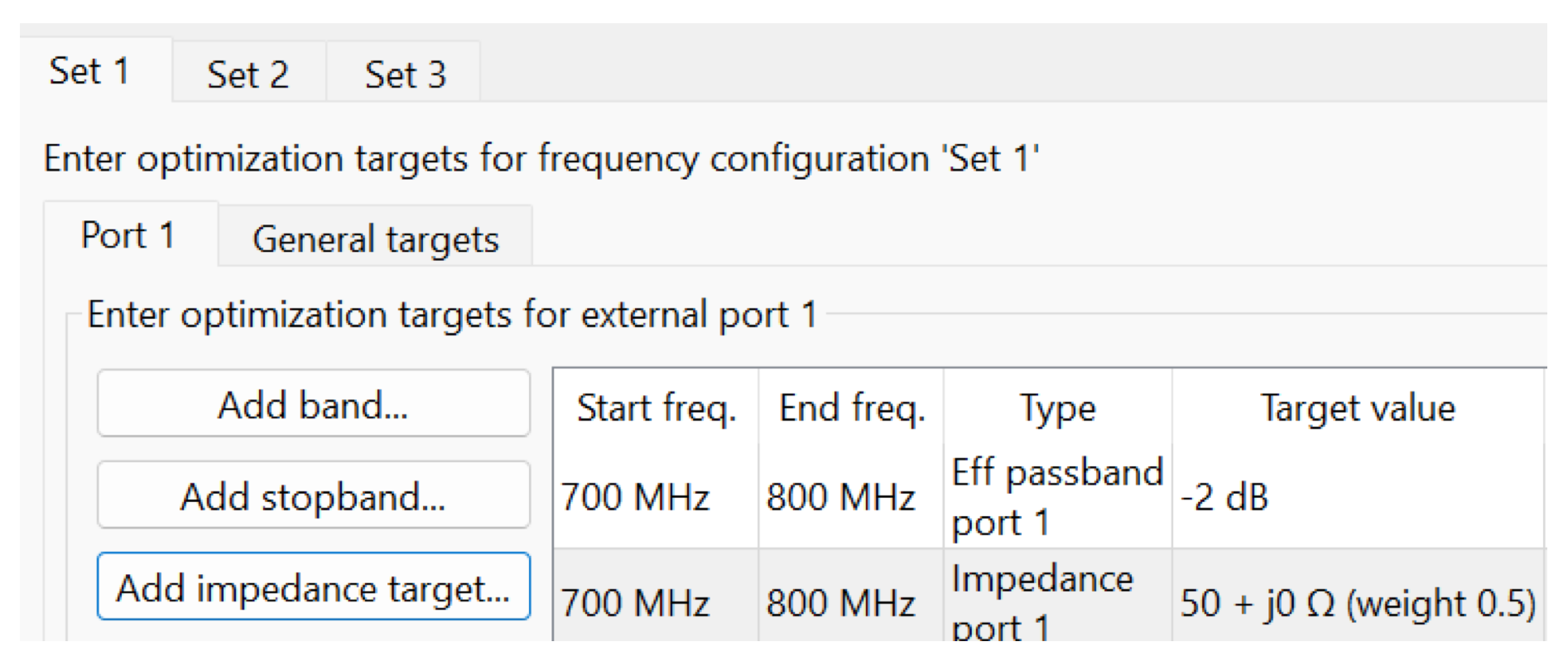
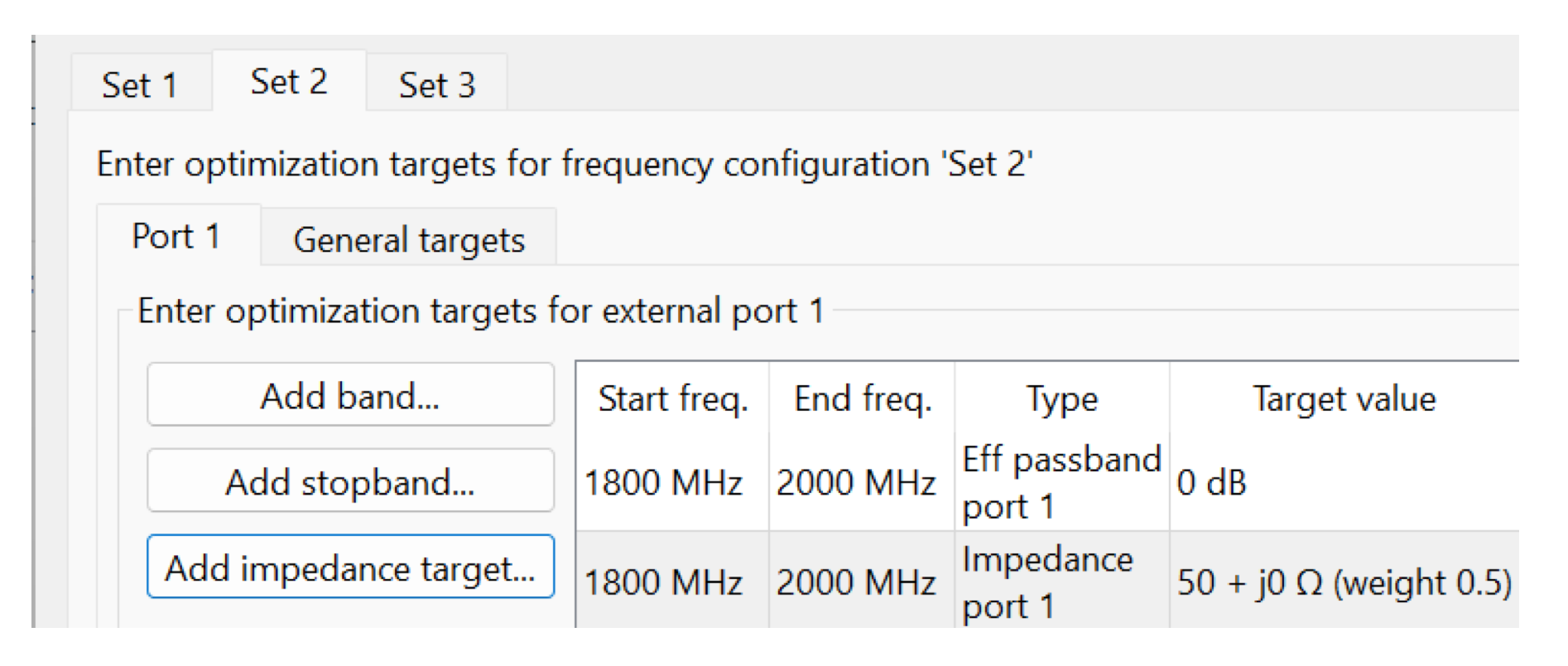
Then you assign the targets, one for each of the frequency configurations. You may use classical efficiency targets, and boost the process with impedance targets. Below, we have examples for set 1 and 2 (set 3 settings are obvious and thus not repeated)
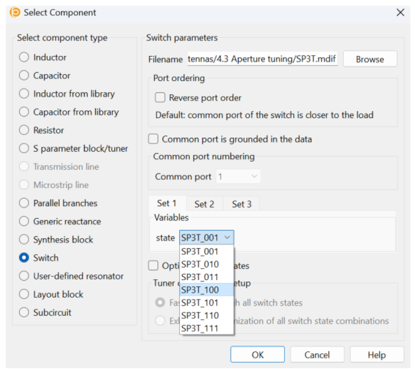
Finally, we need to set the switch to follow the frequency configurations. For example, for frequency configuration set 1, set the switch to state SP3T_100, for set 2 to state SPT3_010 etc.
The tuning port setup now looks like this:
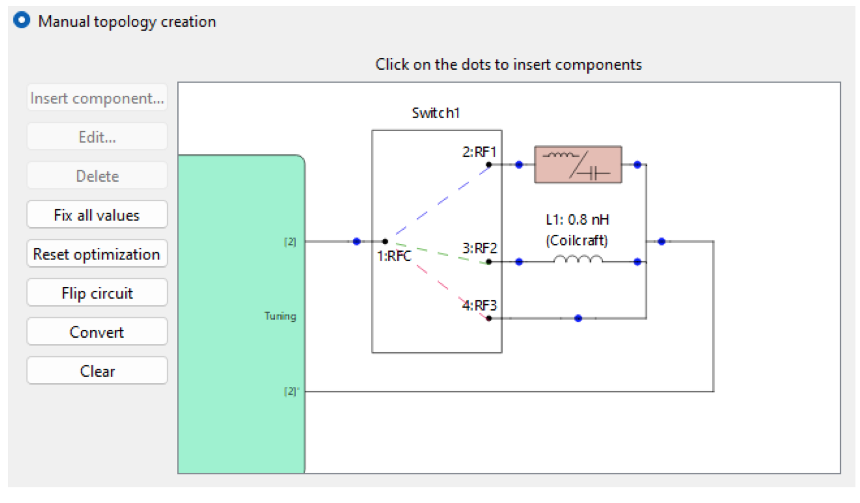
Please remember that that the tuning components at switch ports RF2 and RF3 were deduced from the preassessment results. Different states of the switch (and their corresponding frequency configurations) are shown with colored dashed lines.
Finally, the overall synthesis task looks like this, with the somewhat condensed contents of circuit 2 shown above.

Note how trivially easy it is to ask Optenni Lab to keep the synthesis results the same in the feeding port 1. We simply place an automatic 0-6 component synthesis block to the port, and Optenni Lab takes care of the rest, using the same (but yet to be synthesized) topology for all three frequency configurations and states of the switch.
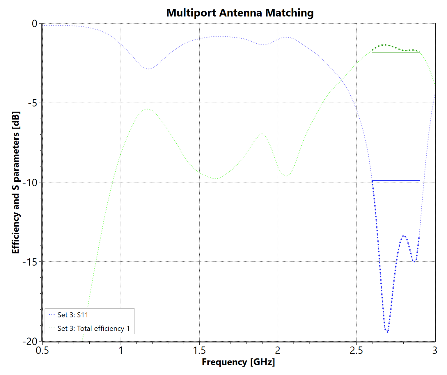
After some 60-90 seconds of number crunching, we get the following promising result.

For example, for the high frequency band, the result is as follows, nicely catering for the needs at that band, only -1.8 dB off from the perfect efficiency result of 0 dB.
We can also study e.g. the power balance diagram at the center of the high band, with the following outcome:
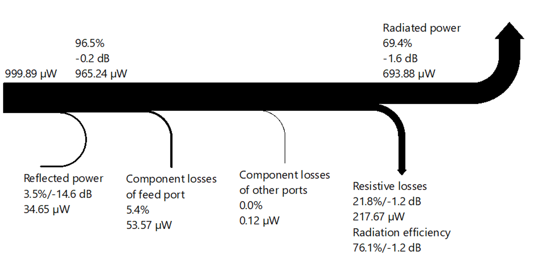
This clearly illustrates that we have achieved more or less perfect matching condition at this band, but the always present resistive losses and component losses make the result less than ideal.
The same observations can be naturally repeated for other bands.
Note how well Optenni Lab keeps the designer up-to-date of his/her design progress. More information means less guessing, less errors, better product quality and a faster time-to-market.
Conclusion
Handling multiple bands in antenna matching, each requiring both identical (static) matching portions, and band-dependent (dynamic) matching portions is very easy with Optenni Lab. All this can be done
- relative to the total efficiency of the antenna which is the true figure of merit of an antenna system, and
- with full synthesis capability for matching and tuning circuit topologies.
We encourage the antenna community to stop wasting time in guessing their matching and tuning networks. Instead, please use Optenni Lab. Hit that Start Free Trial button at Optenni homepage now!
Olli Pekonen
Sales Director
Email: olli.pekonen (at) optenni.com