Optenni – 15 years of innovation in antenna and RF design automation

Optenni – 15 years of innovation in antenna and RF design automation

Posted by Jussi Rahola | 1 June 2024

I founded Optenni Ltd exactly 15 years ago and it has been the most exciting part of my professional career. Optenni has become an established player in the RF and antenna ecosystem, thanks to the work of Optenni employees and the collaboration with our customers, software and hardware partners and component vendors. In this blog article I would like to share some highlights along the journey.

The idea for automated matching circuit synthesis software was born when I was working at Nokia Research Center in Helsinki, Finland. I saw that matching circuits had become an essential ingredient of mobile phone antennas and thus there should be a market for tools to speed up the matching circuit design process and to ensure that the best efficiency of the antenna system is reached.

Optenni was registered as a company in June 2009 and already the following year the initial version of Optenni Lab was released. The first conference trip for Optenni was to the European Conference on Antennas and Propagation (EUCAP2010) organized in Barcelona, Spain, from where the return trip became quite memorable: due to the eruption of the volcano Eyjafjallajökull in Island, instead of a four-hour flight the return trip became a three-day journey by busses, ferries and trains!

Over the years, we have constantly increased the capabilities and features of Optenni Lab. Below you can see the timeline of the major development steps:

  • 2010: Initial version of Optenni Lab with single-port matching circuit synthesis, bandwidth potential for estimating obtainable bandwidth and electromagnetic isolation for calculating worst-case isolation
  • 2011: Component library of inductors and capacitors
  • 2011-2015: Links with leading electromagnetic simulators
  • 2013: Simultaneous multiport matching circuit synthesis
  • 2014: Optimization of tunable matching circuits
  • 2014: Link with network analyzers
  • 2016: Optimization for switchable matching circuits
  • 2017: Optimization of matching circuits for antennas in multiple different usage environments
  • 2019: Support for antenna radiation patterns
  • 2020: Array beamforming optimization and total scan pattern analysis of phased arrays
  • 2021: Effective Isotropic Radiated Power (EIRP) calculations for antenna arrays
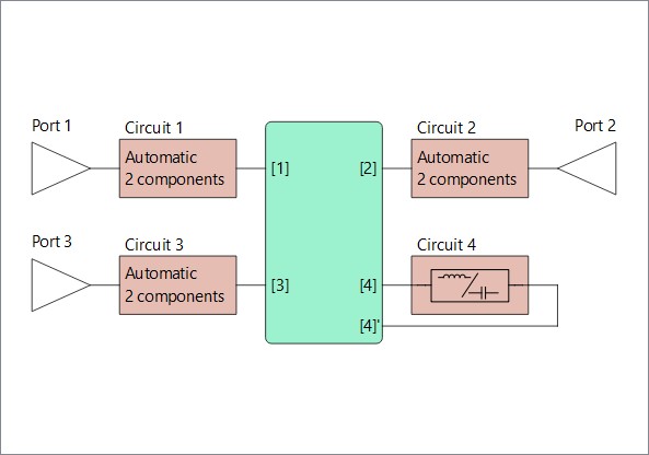
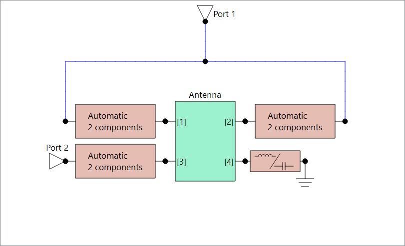
  • 2023: Schematic entry environment to support the synthesis and optimization of complex synthesis task with arbitrary connectivity
  • 2023: Separate control of optimization and plotting frequencies for each optimization run

A central theme in the development of Optenni Lab has been the collaboration between other partners in the wireless ecosystem, which is manifest in the following ways:

  • Simulator links: we have developed links between leading electromagnetic simulators, such as CST Studio Suite by Dassault, HFSS by ANSYS, FEKO by Altair and XFDTD by Remcom. Impedance and radiation pattern data can be sent from these simulators to Optenni Lab with a few mouse clicks. We are also able to send the circuit components optimized by Optenni Lab back to the circuit simulators of CST and HFSS.
  • Network analyzer links: Optenni Lab can connect to network analyzers from leading measurement companies, such as Anritsu, Copper Mountain Technologies, Keysight and Rohde & Schwarz. Optenni Lab can optimize matching circuits in real time based on the measurement data.
  • Radiation pattern measurement data: Optenni Lab can read antenna radiation pattern data from leading antenna measurement systems, such as those by MVG, ETS-Lindgren and Rohde & Schwarz.
  • Component library: Optenni Lab contains an extensive library of realistic inductor and capacitor models from leading component suppliers like Murata, TDK, Taiyo Yuden, Coilcraft, AVX and Johanson Technology.

Optenni Lab has become a powerful circuit simulation tool for antenna and RF design and optimization with the following three unique features:

  • Optenni Lab has built-in circuit synthesis capabilities
  • Optenni Lab understands both circuit quantities (S parameters, voltages, currents) and antenna quantities (efficiencies and radiation patterns)
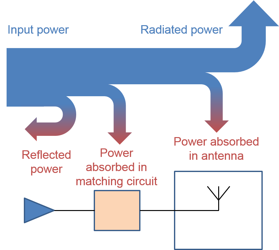
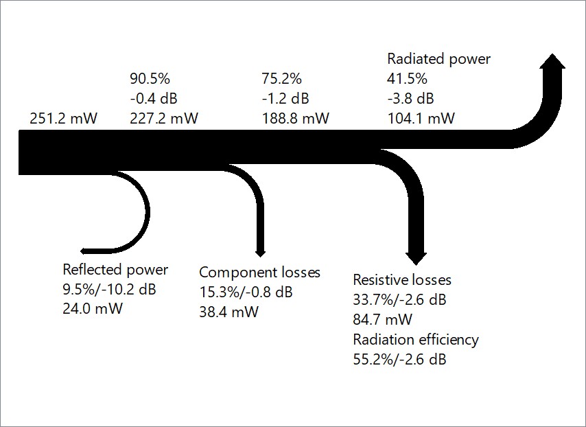
  • Optenni Lab is focused on maximizing the total efficiency of antenna systems

The benefits of Optenni Lab can be summarized in the three following verbs: Explore, Accelerate, Maximize:

  • Optenni Lab’s innovative assessment tools (e.g. bandwidth potential, electromagnetic isolation, total scan pattern) allows you to explore theoretical limits to rank different antenna design candidates and to reveal the theoretical upper limits of wireless performance.
  • Optenni Lab accelerates your design flow by quickly and accurately synthesizing matching circuits using realistic component models. Optenni Lab is especially powerful in the design of frequency tunable RF circuits.
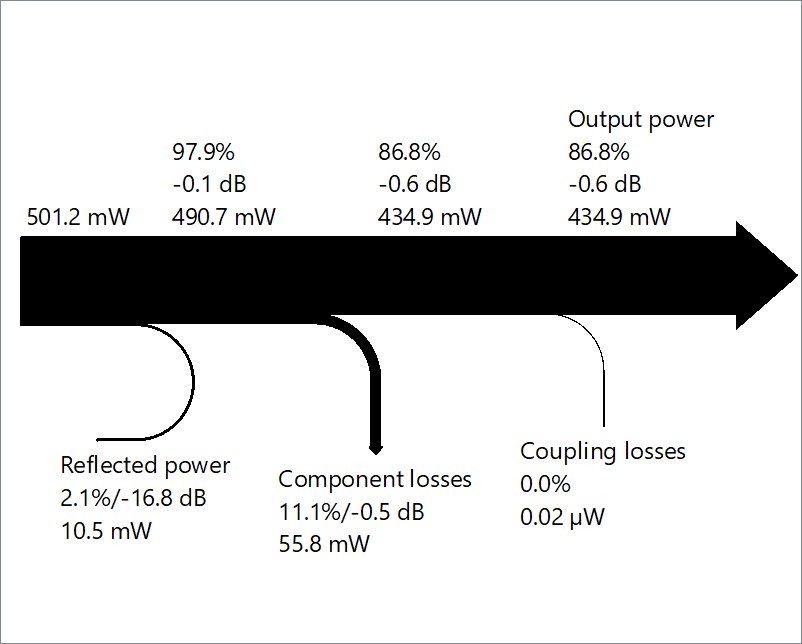
  • Optenni Lab is designed to maximize the wireless performance, taking into account various loss sources and layout effects. Robust designs with respect to varying usage environment of the antenna can automatically be synthesized.

We are happy to see that leading wireless companies worldwide have adopted Optenni Lab to support their design flow. Our customer base ranges from single-person design companies to large technology giants in Europe, North America and Asia. We are proud that 7 out of the 10 biggest technology companies in the world are our customers.

Going forward, we are committed to further innovations in RF and antenna design automation. We are a heavily customer-driven company, and we are complementing customer ideas with our own innovations to broaden the applicability and to increase the usability of Optenni Lab.

To celebrate the 15-year journey we are planning some physical and online events later this year. Stay tuned for additional information on this.

I would like to personally thank all our customers for their collaboration and constructive feedback for the development of Optenni Lab, our partner companies for enabling the interoperability of simulators, measurement data and simulation models and finally the innovative and dedicated Optenni staff who have made our common journey so inspiring and interesting.


CEO Jussi Rahola
Email: jussi.rahola (at) optenni.com


Power Balance Plots and Napoleon

Power Balance Plots and Napoleon

Posted by Jussi Rahola | 18 December 2023

In this blog article, I will present the background and different variants of Optenni Lab’s power balance plots, which are used to illustrate power flow in RF circuits and antennas. But what has Napoleon to do with all this? Read through the blog and find out!

When delivering courses on matching circuit design at various conferences, I have used the following diagram to illustrate the power flow in matching circuits connected to antennas:


With this figure, it is easy to explain that the goal of matching circuit design is not to minimize the reflected power but to maximize the radiated power of the antenna system. The resistive losses of the matching components can indeed reduce the reflected power, but naturally this happens at the expense of radiated power and antenna efficiency.

Based on the above idea, back in 2019 we introduced power balance plots into Optenni Lab so that you can easily see the propagation of power in your antenna system and see the changes when you tune interactively any of the matching components. The figure below shows an example of the power balance plot for a single-antenna system, where also the absolute and relative power levels of the various loss mechanisms are shown numerically.


In addition to single-port matching, Optenni Lab can easily treat antenna systems with an arbitrary number of ports. The starting point is multiport antenna data coming typically from an electromagnetic (EM) simulator. Optenni Lab can synthesize matching circuits for each of the EM ports and wire the circuits to a number of external ports. In addition, Optenni Lab can optimize the type and value of components to be placed in the aperture or tuning ports of the EM model. The two figures below illustrate some possible multiport circuit synthesis setups in Optenni Lab.


Optenni Lab can easily plot the power propagation in multiantenna systems. The multiantenna  power balance plot can show the power lost to other ports (labeled “Coupling losses”) and depending on the setup the component losses can be in some cases shown for the feed port and for the other ports separately.

The animation below shows the power balance plot for the multiport antenna case when the user changes the visualization frequency.

We also generalized the power balance plots to general RF systems, which do not have an antenna component. In this setup, Optenni Lab can easily show the power flow between a pair of external ports, where the goal is to maximize the power coupled to the target port (marked as “Output power”) and the power coupled to any other ports is considered as a loss (labeled “Coupling losses” in the image below).


All the examples above assume that only one port is fed at a time. But Optenni Lab can also calculate the power balance plots for a simultaneous multiport excitation, such as in antenna arrays, where special emphasis needs to be placed on the active reflection coefficient and the dependence of the radiation efficiency on the feeding amplitudes and phases.

How does Napoleon then enter the picture? Well, during the IMS2023 exhibition I was demonstrating Optenni Lab and the power balance visualization to various customers and then two engineers independently remarked that the power balance plots resemble the visualization of the losses of Napoleon’s army during his infamous invasion to Russia during 1812.

Indeed, I studied Wikipedia and discovered the visualization by French engineer Charles Joseph Minard from 1869, which indeed uses related visualization techniques:


Source: Wikimedia commons.


From the visualization one can see the dramatic loss of life during this ill-fated campaign: over 400 000 solders started the march to Russia. Only some 100 000 reached Moscow and out of those only 4000 solders returned alive, others being eliminated by disease, exhaustion, and bitter cold. Quite a path loss!

In summary, we adopted a data visualization technique which is more than 150 years old to describe the power balance in antenna matching circuits and in general RF circuits. If your boss insists on focusing on the minimization of reflected power, you can use these plots to highlight the importance of maximizing the antenna efficiency instead.


CEO Jussi Rahola
Email: jussi.rahola (at) optenni.com

Start your free trial now

Explore – Accelerate – Maximize

Explore – Accelerate – Maximize

Posted by Jussi Rahola | 20 September 2023

With this article I would like to welcome you to the new Optenni blog series. In this blog we will be discussing various matters related to RF circuit synthesis, impedance matching, antenna arrays and our Optenni Lab circuit synthesis software for antenna and RF optimization.

When re-designing the pages, we also re-thought the key messages about our software. The key benefits of Optenni Lab can be condensed in the three verbs: explore, accelerate and maximize.

Using these verbs, let me now explain in more detail what Optenni Lab can offer you.

You may also have noticed a new look and feel for our web pages at www.optenni.com.

Explore theoretical limits:

Optenni Lab has several innovative assessment tools which help to reveal the theoretical upper limits for the wireless performance of your antenna or RF system. If your system requirements are not met with the theoretical upper limits revealed by Optenni Lab, you should likely redesign your antenna radiator structure, and not spend time in vain trying to improve the matching.

The main assessment tools are as follows:

  • Bandwidth potential: using the impedance of an unmatched antenna, the bandwidth potential calculation quickly reveals the obtainable bandwidth of the antenna through a matching circuit as a function of frequency. Thus, you can quickly determine if your antenna can provide the requested impedance bandwidth after it has been matched.
  • Electromagnetic isolation: when working with antenna systems, you may initially think that there is a good isolation between two antenna ports. However, most of the isolation may come from impedance mismatch. The concept of electromagnetic isolation removes the effect of impedance mismatch from the calculation and determines the worst-case isolation for each frequency (when the two antennas are simultaneously matched). In converse, for linear amplifiers, the electromagnetic isolation calculation gives the best possible transducer power gain.
  • Total scan pattern: when working with antenna arrays and beam steering, the beam can only be steered to a certain amount away from the broadside direction before the gain begins to drop and grating lobes start to appear. Optenni Lab implements the total scan pattern calculation, which reveals the maximum gain of the antenna array to any direction. Optenni Lab can also combine the total scan patterns from multiple arrays to determine if they together can provide a more uniform angular coverage of the beams.

Accelerate your design flow:

Accelerating the RF circuit design flow is at the heart of Optenni Lab. Instead of placing and wiring matching components manually, you can leverage the powerful circuit synthesis capabilities of Optenni Lab. After reading in your impedance and radiation data, just specify the desired operation bands and component types, and within seconds Optenni Lab can provide multiple optimized matching circuit topologies. Optenni Lab can optimize broadband and multiband matching circuits also for tightly coupled antenna systems.

The real power of Optenni Lab’s synthesis and optimization algorithms is revealed when tunable and switchable matching circuits are optimized. With Optenni Lab, frequency bands can be grouped into frequency configurations, where each configuration contains the frequency bands which need to be covered by a single switch or tuner state. At the same time, the input port of the system can have a common matching circuit that is to be identical to all states of the system. The optimization of such circuits is a complex task as the total performance depends on the circuit topology, component values and switch and tuner states.

A key part of the acceleration of the design flow is the capability of Optenni Lab to link with leading electromagnetic simulators and measurement equipment. Together with the EM tool vendors we have developed automated links so that simulated S parameters and radiation patterns can be sent from the EM tool to Optenni Lab with a few clicks of the mouse. And in some cases we can send the circuit back to the circuit simulators embedded in the EM tools for further co-simulation.

We also provide links to leading network analyzer models so that you can quickly get the measured data into Optenni Lab and synthesize matching circuits in real time based on the measurements.

Maximize wireless performance:

In impedance matching, the design goal is not to get the best possible impedance match (which can be obtained with sufficiently lossy components), but to transfer maximum amount of power from the antenna or to a load. Optenni Lab’s optimization setup guides you to the maximization of efficiency or maximization of transferred power.

In the optimization we consider all the loss mechanisms in the circuit: impedance mismatch, component losses, coupling to other ports and finite radiation efficiency. Optenni Lab has a wide range of optimization targets for different purposes: passband and stopband efficiency targets, targets to improve the isolation or to move the impedance to a desired location.

For antenna arrays, Optenni Lab is also able to optimize the beamforming coefficients in conjunction with circuit values. The software takes the radiation patterns of each individual element and the coupling between the elements fully into account based on your original simulated or measured data. It is easy to steer the beam to a given direction, control the side lobe levels, nulls and the active reflection coefficient of the array.

More to come:

Stay tuned for additional blog articles from us. We have a lot to tell, as we are very close to releasing Optenni Lab 6.0, our biggest update yet, containing multiple important improvements in circuit synthesis, optimization speed, ease of use and applicability to new problems in RF design.


CEO Jussi Rahola
Email: jussi.rahola (at) optenni.com

Slide

In a matter of seconds, Optenni Lab produces multiple optimized matching circuits for broadband, multiband or tunable matching problems. Optenni Lab can also synthesize and optimize multiple matching circuits for coupled multiantenna systems.

Slide

Optenni Lab can synthesize matching circuit for challenging coupled multiantenna systems, where the matching of all antenna ports must be optimized simultaneously.

Slide

Optenni Lab can display radiation patterns in various formats: Cartesian and polar cuts, two-dimensional pseudocolor plots and 3D plots.

Slide

For tunable antenna design, Optenni Lab uses multiple frequency configurations. Each frequency configuration has its own optimization targets and corresponds to different states of the switches and tuners of the circuit.

Slide

Optenni Lab array module can quickly show the array performance using canonical solutions, such as progressive phase shifts and closed-form amplitude tapering.

previous arrow
next arrow

Start your free trial now